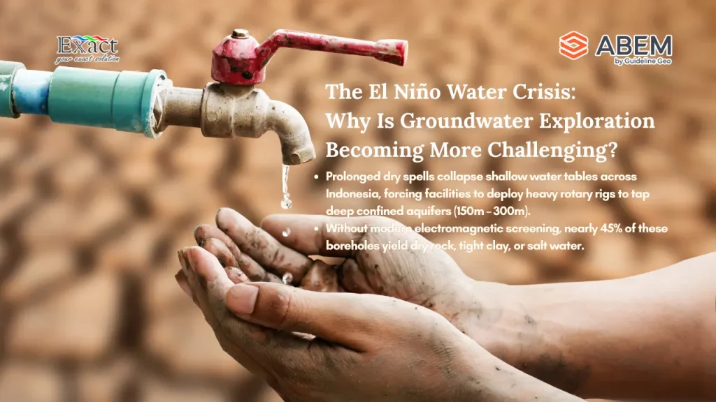
Did you know that during severe El Niño climate cycles across Indonesia, nearly 45% of deep industrial water wells drilled without modern electromagnetic screening fail to produce viable water yields, causing over IDR 500 billion in direct lost capital annually across agricultural, mining, and manufacturing sectors?
When prolonged dry spells grip Sumatra, Java, Kalimantan, and Eastern Indonesia, surface water reservoirs recede and shallow water tables collapse. Industrial processing plants face immediate supply cut-offs, palm oil estates suffer drastic yield reductions, and regional water utilities struggle to supply local communities. In response, facility managers mobilize heavy rotary drilling rigs to tap into deep confined aquifers.
However, searching for water beneath parched terrain using outdated ground survey methods or guesswork frequently leads to a severe financial trap: Dry Hole Drilling. Drilling a single borehole down to 150 or 300 meters without knowing the underlying rock structure can cost anywhere from hundreds of millions to over a billion Rupiah—only to produce dry rock, tight impermeable clay, or salty water.
As geophysicists and field survey leads who have spent the last decade mapping subsurface conditions across Indonesia, we know that searching for deep water during severe droughts requires a different approach. We cannot rely on rainy-season assumptions when topsoil is completely baked dry.
In this guide, we break down proven Deep Groundwater Exploration Solutions During the Dry Season. We share a 7-step approach that combines rapid inductive electromagnetic screening with high-resolution electrical imaging to eliminate drilling failures, protect capital budgets, and secure water supplies when drought strikes hardest.
1. Ditch Rainy-Season Assumptions and Overcome High Contact Resistance
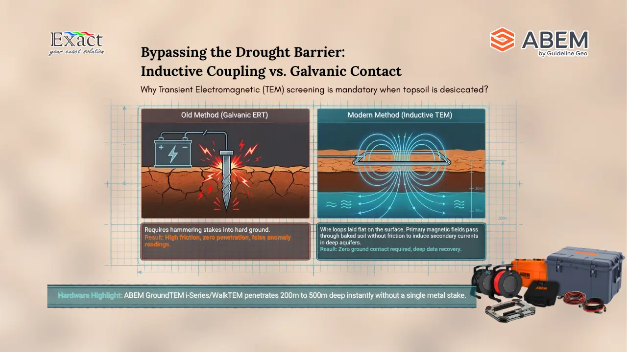
During extended dry periods, the top 5 to 15 meters of soil lose almost all moisture. This desiccation creates a major physical obstacle for standard ground survey tools: High Contact Resistance.
Traditional Electrical Resistivity Tomography (ERT) relies on driving metallic electrode stakes directly into the soil to inject direct electrical current. In moist ground, current flows smoothly between electrodes. However, when topsoil turns into bone-dry sand, baked clay, or loose gravel, electrical resistance at the stake-to-soil boundary spikes dramatically.
When field teams encounter High Contact Resistance:
- Current injection drops to near zero or trips automatic instrument safety shutoffs.
- Receiver channels record high signal noise, generating false anomalies.
- Inversion software creates misleading visual artifacts, causing teams to mistake dry rock fractures for water-bearing sand layers.
| PARCHED SOIL VS. GROUNDWATER SURVEYS | |
| CHALLENGE | : Bone-dry topsoil creates HIGH CONTACT RESISTANCE for metal stakes. |
| IMPACT | : Low current injection, noisy data, false anomaly readings. |
| SOLUTION | : Switch to Inductive Electromagnetic Methods (TEM) that require ZERO galvanic ground contact during initial site scouting. |
To solve this problem, we must change how we collect field data. Instead of forcing galvanic electrical current into hard, dry surface ground during reconnaissance, we use inductive electromagnetic loops that pass signals into the earth without needing metal stakes.
2. Implement a Structured Workflow for Scout and Detailed Surveys
One of the biggest mistakes we see in field exploration is deploying slow, labor-intensive survey setups across vast site areas without prior screening. Covering a 200-hectare plantation or mining concession using standard electrode arrays can take weeks, consuming field budgets before identifying a single target.
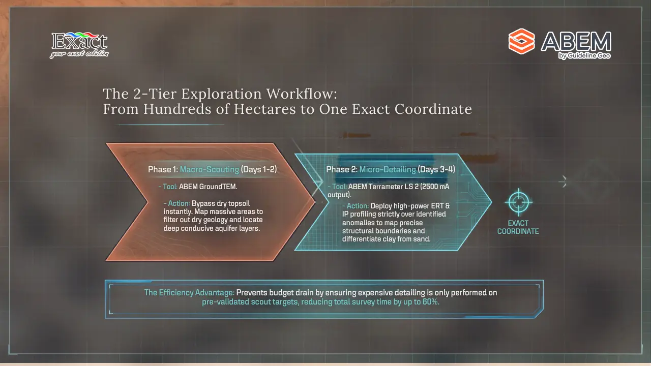
To maximize budget efficiency and survey accuracy, we always apply a two-tier Workflow for Scout and Detailed Surveys:
|
WORKFLOW FOR SCOUT AND DETAILED SURVEYS |
|
STAGE 1: SCOUT PHASE (Rapid Reconnaissance) – Instrument: ABEM GroundTEM i-Series or WalkTEM 2. – Method: Transient Electromagnetic (TEM) inductive loops. – Speed: Cover large areas in days; bypass dry topsoil instantly. – Goal: Map deep conductive layers and locate prospective aquifer zones. ↓ |
|
STAGE 2: DETAIL PHASE (Structural & Boundary Profiling) – Instrument: ABEM Terrameter LS 2. – Method: Multi-electrode ERT & Induced Polarization (IP). – Speed: Targeted 2D/3D cross-sectional profiles over identified anomalies. – Goal: Map exact aquifer boundaries, clay aquitards, and water quality. ↓ |
|
STAGE 3: DRILLING SITE VALIDATION – Integrated model cross-checks & field-based quality control. – Goal: Select exact borehole coordinates, casing depth, and target yields. |
By dividing campaigns into clear Scout and Detail phases, we reduce overall survey time by up to 60% while increasing drilling success rates close to 100%.
3. Deploy the ABEM GroundTEM i-Series for Rapid Inductive Scouting
During the Scout Phase, our main goal is speed and penetration depth. We need a system that completely ignores dry surface soil, penetrates hundreds of meters deep, and deploys rapidly with a small crew.
For this phase, we rely on Transient Electromagnetic (TEM) technology, specifically the ABEM GroundTEM i-Series and the ABEM WalkTEM 2 systems.
TEM systems operate by placing wire loops flat on the ground surface. A transient current running through the transmitter loop creates a primary magnetic field. When turned off abruptly, this primary field induces secondary electrical eddy currents in conductive underground layers, such as water-bearing sand, gravel, or fractured rock formations. Because magnetic fields pass through dry topsoil without friction, TEM signals suffer zero loss from dry surface ground.
|
HOW TEM INDUCTIVE COUPLING WORKS |
|
1. Transmitter Loop (laid flat on ground) creates primary magnetic field. 2. Current cuts off rapidly, inducing secondary eddy currents in ground. 3. Underground currents generate a secondary magnetic field. 4. Receiver Coil records signal decay over time to reveal deep conductivity. |
|
➜ ZERO STAKES REQUIRED | ZERO SIGNAL LOSS FROM DRY TOPSOIL |
Why We Use the ABEM GroundTEM i-Series for Scouting
The ABEM GroundTEM i-Series (including the GroundTEM i5, GroundTEM i10, and GroundTEM i20) is designed specifically for rapid, user-friendly, app-controlled groundwater surveys:
- No Ground Contact Needed: Because the system uses wire transmitter loops and flexible receiver coils laid directly on dry terrain, field teams leave zero footprints and do not need to hammer metal stakes into baked ground.
- Dual-Moment Measurement Technology: All ABEM GroundTEM i-Series units automatically switch between low-current and high-current pulses within a single survey cycle. Low-moment pulses resolve shallow hydrogeological layers, while high-moment pulses penetrate deep into target zones, combining both into one clear dataset.
- Scalable Power for Every Target Depth:
- GroundTEM i5: Features a maximum output of 5A through 20x20m or 40x40m loops, providing an affordable entry-level option for shallow to medium aquifer mapping.
- GroundTEM i10: Unlocks a maximum output current of 10A without adding size or weight, comfortably penetrating depths of 200+ meters.
- GroundTEM i20: Delivers 10A current output configured for deeper target investigations reaching down to 500 meters.
- Lightweight One-Box Design: Controlled wirelessly via a smartphone or tablet interface, a two-person team can easily carry and operate the lightweight equipment across rough, inaccessible terrain.
Using the ABEM GroundTEM i-Series in Stage 1 allows us to screen large land areas quickly, filter out dry geological formations, and highlight deep conductive zones that indicate water-bearing aquifers.
4. Perform High-Resolution 2D and 3D Imaging with the ABEM Terrameter LS 2
Once TEM scouting identifies deep conductive anomalies, we move to Stage 2 of our Workflow for Scout and Detailed Surveys: detailed structural imaging.
While TEM excels at sounding deep conductor layers, Electrical Resistivity Tomography (ERT) and Induced Polarization (IP) excel at mapping continuous 2D/3D horizontal and vertical geological cross-sections. This detail phase allows us to map rock structures, fault zones, clay boundaries, and salt water interfaces.
To execute high-resolution ERT and IP imaging under dry field conditions, we deploy the ABEM Terrameter LS 2.
| ABEM TERRAMETER LS 2 ADVANTAGES | |
| 1. COMPACT TRANSMITTER POWER | : Up to 250 W, 2500 mA, and ±600 V output to force signal through dry, resistive soil. |
| 2. 24-BIT RECEIVER & 3 VOLTAGE RANGES | : Digitize weak signals accurately amidst background noise. |
| 3. ON-SCREEN ACTIVE GUIDANCE | : Embedded mentor guides technicians through troubleshooting, diagnostic checks, and setup verification in the field. |
| 4. MULTI-ELECTRODE CAPACITY | : Controls up to 81 active internal electrode channels for seamless 2D and 3D profiling. |
How the ABEM Terrameter LS 2 Handles High Resistance
The ABEM Terrameter LS 2 includes hardware engineering features specifically built to overcome dry surface resistance and produce clean subsurface models:
- High-Power Constant Current Transmitter: Featuring output power up to 250 W, maximum current up to 2500 mA, and maximum voltage up to ±600 V (1200 V peak-to-peak), the LS 2 forces current through highly resistive dry ground where standard instruments fail.
- Advanced 24-Bit A/D Receiver: The receiver uses a 24-bit digitizer across three dynamic voltage ranges (±2.5V, ±15V, and ±600V), capturing tiny voltage signals even when ground current input is restricted by surface dryness.
- Built-in Active Guidance System: Field conditions can change unexpectedly. The Terrameter LS 2 features on-screen Active Guidance accessible by pressing the Guide button. This feature provides connection checklists, electrode contact checks, and real-time troubleshooting steps directly on screen to keep data collection accurate.
- Rugged IP66 Casing: Housed in a tough aluminum case built to IEC IP66 standards, the instrument operates reliably in harsh, hot field environments ranging from -20°C to +70°C.
Differentiating Underground Formations
By analyzing 2D resistivity and IP profiles from the ABEM Terrameter LS 2, we can distinguish between subsurface formations that often confuse basic survey tools:
|
Subsurface Layer |
Typical Resistivity Range |
Chargeability (IP Signal) |
Hydrogeological Interpretation |
|
Dry Surface Soil / Loose Sand |
Very High (> 1,000 Ω⋅m) |
Very Low |
Dry unproductive surface zone |
|
Hard Unfractured Bedrock |
High (> 500 Ω⋅m) |
Low |
Impermeable rock cap / barrier |
|
Saturated Clay / Shale |
Low (1 – 15 Ω⋅m) |
High |
Impermeable clay aquitard (holds water, won’t yield) |
|
Freshwater Aquifer (Sand/Gravel) |
Medium (30 – 150 Ω⋅m) |
Low |
Primary target for high-yield drilling |
|
Saline / Brackish Aquifer |
Extremely Low (< 5 Ω⋅m) |
Low |
Contaminated salty water layer (must be sealed) |
Measuring both resistivity and Induced Polarization (IP) prevents mistaking an impermeable, sticky clay layer for a productive freshwater aquifer. Clay layers exhibit high chargeability due to membrane polarization, whereas clean sand and gravel aquifers show low chargeability.
5. Leverage Real-Time Inversion and In-Field Processing
In traditional geophysical workflows, field teams collect raw readings, store them on memory cards, and send them to an off-site office for processing days later. If data noise or cable disconnects occur, the team only discovers it after leaving the site, leading to costly re-surveys.
Modern Deep Groundwater Exploration Solutions During the Dry Season require real-time processing and model inversion directly in the field.
| BENEFITS OF REAL-TIME DATA INVERSION | |
| 1. INSTANT MODEL VISUALIZATION | : View smooth 1D/2D ground resistivity profiles directly on control screens while collecting data. |
| 2. IMMEDIATE QUALITY CONTROL | : Spot electromagnetic interference or cable bad contacts instantly and re-take soundings on the spot. |
| 3. ON-SITE DECISION MAKING | : Verify aquifer depths with project managers before demobilizing crews, saving days of report waiting time. |
Using control apps on the ABEM GroundTEM i-Series or onboard inversion features on the ABEM WalkTEM 2 and ABEM Terrameter LS 2, we generate resistivity models and depth-of-investigation (DOI) plots within minutes of completing soundings.
If local electromagnetic noise from power lines or dry ground skews a measurement, we see it on screen right away. We can adjust loop layouts, increase stack counts, or run diagnostic relay tests on the spot, ensuring that every dataset brought back to the office is verified and complete.
6. Conduct Rigorous Drilling Site Validation
The final step in our process is Drilling Site Validation. This validation phase ensures that visual. Before recommending a drilling coordinate, our geophysics team runs a 4-point validation check:
- Cross-Method Correlation: We overlay 1D TEM depth soundings from the ABEM GroundTEM i-Series onto 2D ERT cross-sections from the ABEM Terrameter LS 2. Where both independent methods show matching conductive anomalies, target confidence reaches its highest level.
- Stratigraphic Boundary Marking: We pinpoint the exact starting depth and thickness of the water-bearing target layer. This allows drilling contractors to prepare accurate casing schedules, filter pack volumes, and well screen lengths before drilling begins.
- Water Quality Verification: We evaluate calculated ground resistivity values against regional hydrogeological data to confirm freshwater conditions, avoiding layers that contain brackish or salty water.
- Surface Rig Logistics: We inspect physical site access, overhead power clearances, and ground stability to confirm that 20-ton rotary drilling rigs can set up safely over chosen coordinates.
By strictly following this Drilling Site Validation protocol, facility owners eliminate Dry Hole Drilling risks, turning dry land into a secure, long-term water source.
7. Strategic Implementation Across Key Industrial Sectors in Indonesia
Applying this structured geophysical exploration strategy delivers clear, practical benefits across major economic sectors in Indonesia:
|
SECTOR-SPECIFIC APPLICATIONS |
|
INDUSTRIAL MANUFACTURING & PROCESSING – Need: Continuous high-volume water supply for boilers, cooling, and washing. – Solution: Map deep confined aquifers below industrial zones without relying on over-pumped shallow water tables.
|
|
PALM OIL & AGRICULTURAL ESTATES – Need: Irrigation and mill processing water during 6-month dry seasons. – Solution: Use ABEM GroundTEM i-Series to scout thousands of hectares fast, locating high-yield alluvial sand aquifers along river basins.
|
|
MINING CONCESSIONS & REMOTE CAMPS – Need: Potable camp water and dust suppression supplies in hard rock geology. – Solution: Combine TEM and ERT to locate deep fractured bedrock aquifers and fault-hosted groundwater reservoirs beneath thick cap rocks.
|
|
MUNICIPAL & REGIONAL WATER UTILITIES / PDAM – Need: Emergency drought relief supplies for local communities. – Solution: Rapidly identify clean freshwater zones and monitor coastal seawater intrusion to protect long-term public well fields.
|
Real-World Field Outcome: Securing Water for an Agro-Industrial Facility
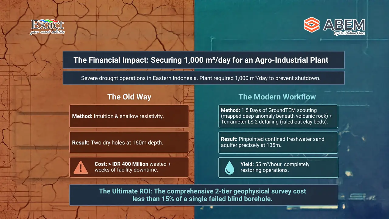
During a recent severe dry season in Eastern Indonesia, a major agricultural processing plant faced a critical water shortage. Their daily operations required 1,000 cubic meters of freshwater. Local drillers had already drilled two exploratory wells based on basic dowsing and shallow resistivity checks. Both wells resulted in Dry Hole Drilling at 160 meters depth, wasting over IDR 400 million in capital and costing weeks of operational downtime.
Our team was called in to execute our Workflow for Scout and Detailed Surveys:
- Scout Phase: We deployed the ABEM GroundTEM i10 across a 120-hectare area. In just 1.5 days, TEM soundings mapped a deep conductive aquifer layer at 130 to 180 meters depth beneath a dense volcanic rock layer that shallow surveys had completely missed.
- Detail Phase: We ran targeted ERT and IP lines with the ABEM Terrameter LS 2 across the anomaly, mapping fault boundaries and confirming low chargeability (ruling out clay beds).
- Validation & Drilling: We performed Drilling Site Validation and pinpointed exact drill coordinates. The drilling rig hit a confined freshwater sand aquifer at 135 meters depth, delivering a yield of 55 cubic meters per hour. The entire geophysical survey cost less than 15% of a single failed borehole.
Partner with Authorized Subsurface Experts: PT. Exact Global Teknologi
As the official distributor for ABEM instruments in Indonesia, PT. Exact Global Teknologi equips professionals with the world’s most trusted geophysical technology. We provide not just the hardware, but the technical training and field expertise required to solve Indonesia’s toughest groundwater challenges.
Reach Out to Us:
- Website:exactglobal.co.id
- Email Marketing: marketing@exactglobal.co.id
- WhatsApp: +62 812-9252-3900
Frequently Asked Questions (FAQ)
Q1: Why does Transient Electromagnetic (TEM) work better than traditional Geolistrik (ERT) on dry ground?
Traditional Geolistrik (ERT) requires direct galvanic contact using metal electrodes driven into the soil. During severe droughts, dry surface soil creates High Contact Resistance, blocking current flow and corrupting readings. TEM uses wire loops laid flat on the ground to pass secondary magnetic fields into the earth. Because magnetic fields pass through dry topsoil without friction, surface dryness does not affect TEM signal quality.
Q2: Can the ABEM GroundTEM i-Series reach deep aquifers beneath hard rock or volcanic layers?
Yes. The ABEM GroundTEM i-Series uses dual-moment technology and high transmitter power outputs. The GroundTEM i10 penetrates depths of 200+ meters, while the GroundTEM i20 penetrates down to 500 meters, making them ideal for finding deep aquifers beneath dense volcanic cap rock, dry sand, or hard basalt.
Q3: How does the ABEM Terrameter LS 2 overcome dry ground resistance during detailed surveys?
The ABEM Terrameter LS 2 features a compact 250 W constant-current transmitter capable of delivering up to 2500 mA and ±600 V output. This high output pushes electrical current through resistive surface ground. Its 24-bit receiver and three dynamic voltage ranges accurately digitize weak return signals amidst noise.
Q4: What is the main cause of “Dry Hole Drilling” during deep well construction?
Most dry holes happen when drilling sites are chosen based on intuition, dowsing, or shallow low-resolution surveys that cannot differentiate between water-bearing sand, tight clay layers, or solid rock. Applying our Workflow for Scout and Detailed Surveys using combined TEM and ERT/IP technology eliminates this guesswork.
Q5: How long does a full Scout and Detail survey take for a 100-hectare industrial site?
Using the ABEM GroundTEM i-Series for Stage 1 scouting, we can cover a 100-hectare site in 1 to 2 days. Stage 2 detailed ERT/IP mapping over target anomalies with the ABEM Terrameter LS 2 takes another 1 to 2 days. You receive validated drilling coordinates in less than a week.
Q6: Can geophysical surveys tell the difference between freshwater and saltwater aquifers?
Yes. Electrical resistivity values drop significantly in saline water due to high dissolved salt concentration. By comparing calculated ground resistivity values with Induced Polarization (IP) data, we can separate clean freshwater aquifers from saline intrusion zones or clay layers.
Q7: How can we buy, rent, or request survey services using ABEM equipment in Indonesia?
You can contact PT. Exact Global Teknologi, the authorized distributor for ABEM and Guideline Geo products in Indonesia. We offer sales, rentals, field survey services, data processing, and operator training. Visit us www.exactglobal.co.id, email marketing@exactglobal.co.id, or contact us on WhatsApp at +62 812-9252-3900.