We’ve all been there.
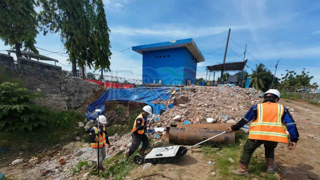
It’s a hot afternoon on a project site in Jakarta. We finish a long GPR scan line over a busy road. The Project Manager walks over, wipes sweat from his forehead, and looks at our screen. He frowns. “That’s it? Where’s the pipe? It just looks like black and white static.”
It’s the most common moment of confusion in our industry. People expect Ground Penetrating Radar (GPR) to work like a medical X-Ray—click a button, and bam—a perfect picture of a pipe appears on the screen. But that’s not how it works. GPR doesn’t take photos. It paints a picture using physics.
At PT. Exact Global Teknologi, we spend a lot of time teaching this difference. As the distributors for Guideline Geo (MALÅ) in Indonesia, we don’t just hand over the box and wish you luck. We help you understand what the machine is actually saying.
Here is the guide to reading the ground, finding the “anomalies,” and understanding why GPR is more about listening than looking.
1. The Echo: We Are Listening, Not Looking
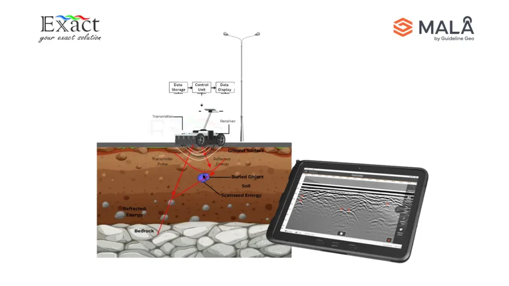
To really get Understanding How Georadar/GPR Works, you have to change your mindset. Imagine you are standing in a dark cave. You can’t see the back wall. So, you shout “Hello!” and wait. A second later, you hear “Hello!” bounce back.
- You know the wall is there because the sound came back.
- You know how far away it is by how long it took.
GPR is exactly the same, but instead of sound, we use radio waves.
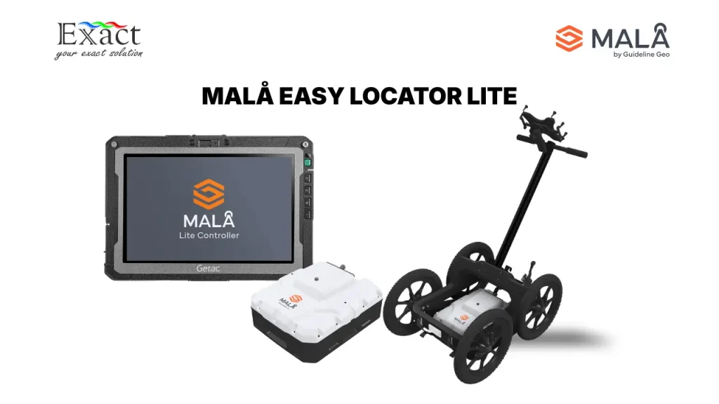
When we push a MALÅ GroundExplorer (GX) or MALÅ Easy Locator Core unit across the pavement, the antenna shoots a tiny pulse of energy into the ground. That pulse travels down until it hits something different—a pipe, a rock, or a layer of wet clay. Part of that energy keeps going, but part of it bounces back to the surface.
The machine records the echo. What you see on the screen isn’t the object itself; it’s the record of the echo. We are mapping how long it takes for the signal to return. That’s why we call them “anomalies.” It’s a disturbance in the signal, not a photo of a pipe.
2. The Contrast: Why Plastic Pipes are “Ghosts”
This is the tricky part, especially in Indonesia. Why does the radar see a metal pipe clearly but struggle to see a plastic water pipe? It’s all about Contrast. Think of it like seeing a polar bear in a snowstorm. White bear, white snow. Low contrast. It’s hard to see. Now think of a black bear in the snow. High contrast. Easy to see.
In GPR language, we call this the Dielectric Constant.
- Metal is like the black bear. It reflects almost everything. Bang! Bright signal on the screen.
- Plastic (PVC) and Water are often like the polar bear. Their “electrical density” is very similar to the wet clay surrounding them. The reflection is weak.
This is where your equipment choice makes or breaks the project. Indonesian soil is often wet and clay-heavy, which eats up radar signals.
If you use a basic GPR, that weak reflection from a plastic pipe gets lost in the background noise. This is why we rely on the MALÅ GX with HDR (High Dynamic Range). The HDR tech is like putting on special glasses that help you spot the polar bear in the snow. It cleans up the background static so even the faint “ghost” signals of plastic pipes stand out.
3. The Arch: Why Pipes Look Like Upside-Down “U”s
If you are looking for a round circle on the screen, you’re never going to find it. Instead, you look for an arch shape. We call it a Hyperbola. Why? It’s simple geometry.
Imagine the MALÅ cart is rolling toward a buried pipe.
- Approaching: The radar “sees” the pipe ahead of it. The signal travels at an angle. It’s a longer distance.
- On Top: Now you are directly over it. The signal goes straight down and up. Shortest distance.
- Leaving: You roll past. The signal travels at an angle again. Longer distance.
On the screen, depth is actually time.
- Long time = deeper on the screen.
- Short time = higher on the screen.
Connect those dots, and you get an arch.
The Golden Rule: The pipe is exactly at the peak of the arch. The “tails” going down the sides are just the history of you walking towards and away from it. Ignore the tails. Mark the peak. That’s where you dig.
4. Speed: The Secret to Knowing Depth
The radar doesn’t actually know how deep an object is. It only knows how long the echo took to return (in nanoseconds).
To get depth in meters, we have to tell the machine the Speed (Velocity) of the soil.
- Radar moves fast in dry sand.
- Radar moves slow in wet clay.
If you get the speed wrong, your depth number will be wrong. You might tell the excavator to dig at 1.5 meters, but the pipe is actually at 1 meter. That’s how accidents happen.
The MALÅ software has a really cool tool for this called “Hyperbola Fitting.” You literally drag a digital curve over the real arch on your screen. When they match, the software calculates the exact speed of that specific soil. It takes the guesswork out of the depth calculation.
5. The Trade-Off: You Can’t Have It All
One of the first things we ask a client is: “What are you looking for, and how deep is it?”. You can’t use the same antenna to find a tiny fiber optic cable and a deep mining tunnel. It’s a trade-off.
- High Frequency: Great detail. You can see cracks in concrete. But the signal dies out fast (shallow).
- Low Frequency: Goes deep (10+ meters). But the image is blurry. You’ll miss small cables.
Most utility jobs in Indonesia use a “Mid-Range” frequency (around 450 MHz). It’s the Goldilocks zone—good detail for pipes, decent depth for road work.
We like the MALÅ ProEx system for professional survey teams because it’s modular. You can swap the antenna in two minutes. One minute you’re scanning a concrete slab, the next you’re mapping deep geology. It’s one brain with many eyes.
6. The Noise: Dealing with Indonesian Soil
Let’s be real about the ground here. It rains a lot. We have salt water near the coast. We have heavy red clay. Wet, salty, or clay soils create “Noise.” On the screen, it looks like horizontal bands of fuzz or random speckles. It can hide the arches you’re looking for. This is where the human element comes in. A newbie might see a reflection from a tree root or a buried rock and think, “Aha! A pipe!”
So, how do we tell them apart? Patterns. A pipe is a long line. A rock is just a dot. To be sure, we never just scan one line. We scan a grid.
- If we see an arch at 5 meters on Line 1…
- And another arch at 5 meters on Line 2…
- And another on Line 3…
We connect the dots. That’s a pipe. If the arch appears once and then disappears, it’s probably just a rock or some old debris.
The MALÅ Vision makes this easy makes this easy. We tag these spots as we walk, and the software draws the line for us. It turns isolated dots into a clear path.
7. The Final Step: Turning Squiggles into Maps
The final piece of Understanding How Georadar/GPR Works is realizing that the raw data on the screen isn’t the final result. While the real-time view is great for marking the ground with paint, the real magic happens back in the office. We take that data and clean it up. We filter out the background fuzz. We boost the weak signals from deep down.
This is when we turn “anomalies” into “maps.” We can create 3D views where the client can actually see the pipes running under the road. But remember: that image is an interpretation based on the signal data. It takes a skilled human to build it.
The Machine Sees the Signal, You See the Solution
A violin doesn’t make music by itself; it needs a player. GPR is the same. The MALÅ unit is the finest instrument on the market for detecting subsurface anomalies, but it needs your eyes and your judgment to turn those signals into answers. That’s the shift we want to see in the industry. We want operators who aren’t just looking for a magic X-Ray image, but who understand the physics of the ground they are standing on.
At PT. Exact Global Teknologi, our job is to make sure you have the best gear and the right knowledge to use it. Because when you understand the anomalies, the invisible becomes visible. Let’s get to work.
PT. Exact Global Teknologi Sole Distributor of Guideline Geo / MALÅ in Indonesia Safe. Accurate. Professional.