Our surveying, mapping, and construction world today demands much more precise and safer work standards. We are slowly leaving behind conventional measurement work that consumes a lot of time and poses high physical risks. In its place, we are now stepping into a new era driven by fully digital reality capture and monitoring solutions.
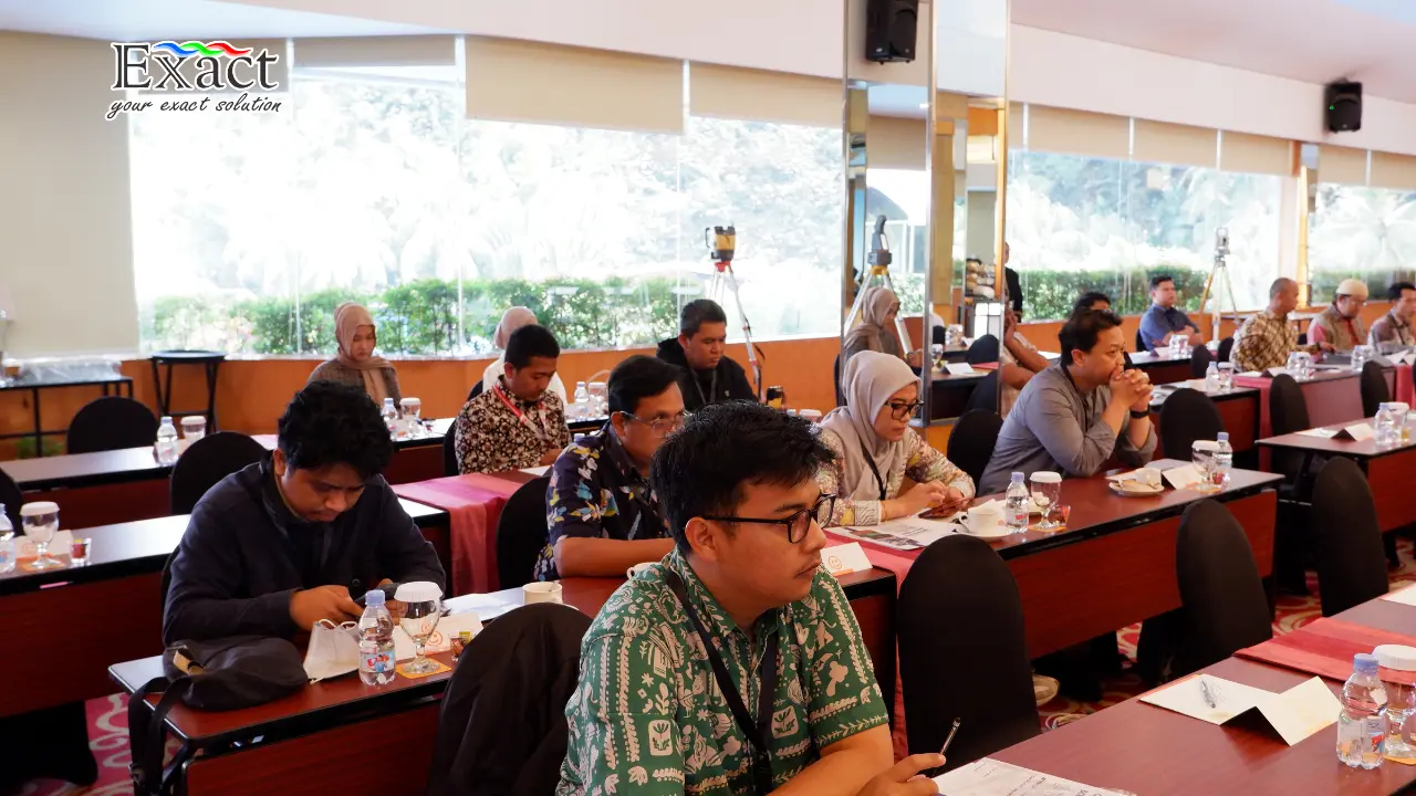
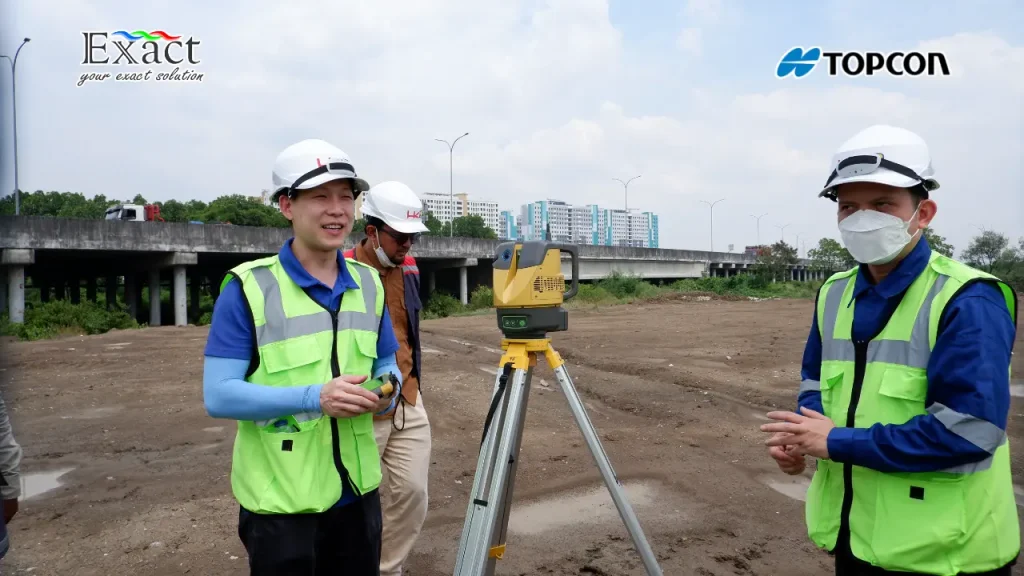
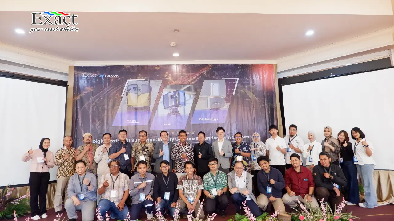
In the One Day Seminar titled “Digitalization in Surveying: Reality Capture & Monitoring in One Session” organized by PT. Exact Global Teknologi in Jakarta, we were invited to see this technological leap firsthand. Together with a team of experts from Topcon Positioning Malaysia and Mr. Agung Syetiawan, an Associate Researcher from the National Research and Innovation Agency (BRIN), we dissected how smart instruments and modern software can simplify our workflow in the field.
Let’s discuss the six main pillars that we can apply to optimize our current mapping projects.
The New Standard of Measurement: Terrestrial Laser Scanner (TLS)
The Terrestrial Laser Scanner (TLS) is a ground-based mapping device that completely changes the way we record field data. This tool works using the principle of an active sensor. Its operation is very logical; it emits electromagnetic waves in the form of laser pulses to the object’s surface, then captures the reflection back to obtain highly accurate distance values.
From these distance values, combined with vertical (pitch and roll) and horizontal (heading) angles, the machine calculates the X, Y, and Z coordinate transformations. The final result is a highly dense collection of millions of 3-dimensional coordinate points, which we know as a point cloud.
Why should we start using the Terrestrial Laser Scanner (TLS) instrument compared to conventional GNSS or Total Station methods? The answer lies in efficiency and safety:
- Contactless Safety: Field data acquisition uses remote sensing principles without having to physically touch the object. We don’t need to climb steep cliffs or stand in the middle of a busy highway.
- Spatial Data Density: The quality of the spatial resolution produced is much higher and more detailed. When we calculate stockpile volumes, the results are very realistic. Conventional methods often provide unrealistic volume calculations because the number of sample points is very limited.
- Zero Operational Disruption: The scanning and data reception process runs relatively smoothly without disrupting the operational pace of heavy machinery or industrial operations around us.
The Spectrum of LiDAR Technology Applications
The heart of the 3D scanner is LiDAR Technology (Light Detection and Ranging). We can mount this technology on various airborne and ground platforms, depending on the scale of our project.
We can use Spaceborne platforms at an altitude of 600 km, Airborne platforms at 1 km, or use drones (UAVs) to fly below 500 meters. However, to achieve the highest accuracy at ground level, we use the Terrestrial platform, which provides very sharp vertical accuracy ranging from 1 to 10 centimetres.
The application of LiDAR Technology is very broad, especially for mapping the progress of open-pit mining. We can periodically monitor several crucial elements:
- Monitoring newly cleared forest areas (land clearing).
- Calculating the daily progress of overburden stripping before we enter the mineral excavation zone.
- Monitoring disposal areas and material stockpiles.
- Checking mine water management facilities, such as drainage channels, sump ponds, and settling ponds.
The Differences Between DSM and DTM in Ground Classification
After we finish scanning the field, the raw data we receive is a recording of all objects that successfully reflected the laser. This initial data is still filled with non-topographical objects such as dense trees, power poles, moving vehicles, and project buildings. We cannot directly use this raw data to design roads or calculate elevations.
Therefore, we need to perform software processing to execute point cloud classification, and this is where we must fully understand the Differences Between DSM and DTM in Ground Classification:
- Digital Surface Model (DSM): This is a digital surface elevation model that still includes buildings, tree canopies, and all obstacle objects standing above the ground.
- Digital Terrain Model (DTM): DTM is a model that only displays the bare earth surface.
To transition from DSM to DTM, we command the software to execute the Ground Classification algorithm. The system will automatically separate point group classes of vegetation and buildings, and then filter them out. This “obstacle removal” process gives us a clean topographic relief profile of the bare ground.
Applying the understanding of the Differences Between DSM and DTM in Ground Classification greatly saves us from the risks of base building design miscalculations and earth excavation quantity measurement errors.
Getting to Know the Smart Instrument Line-up: CR-P1, ESN-100, and EliteScan T1000
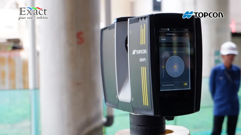
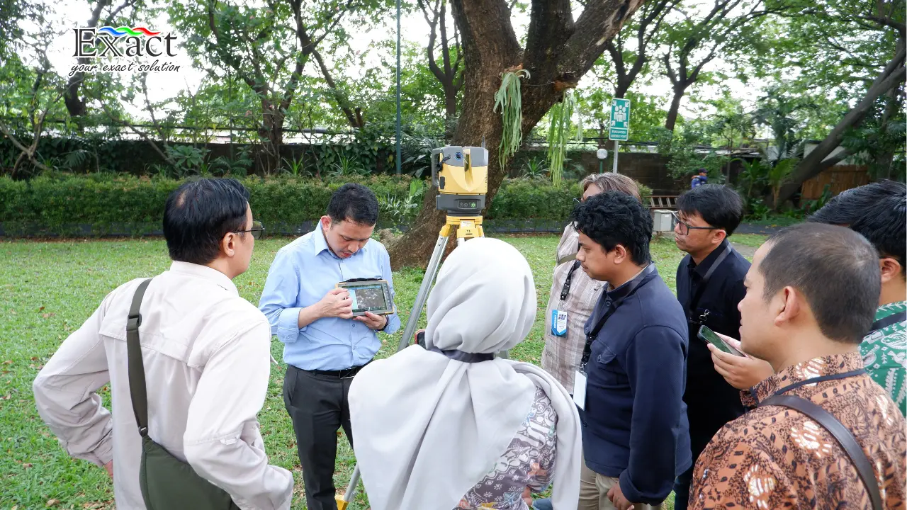
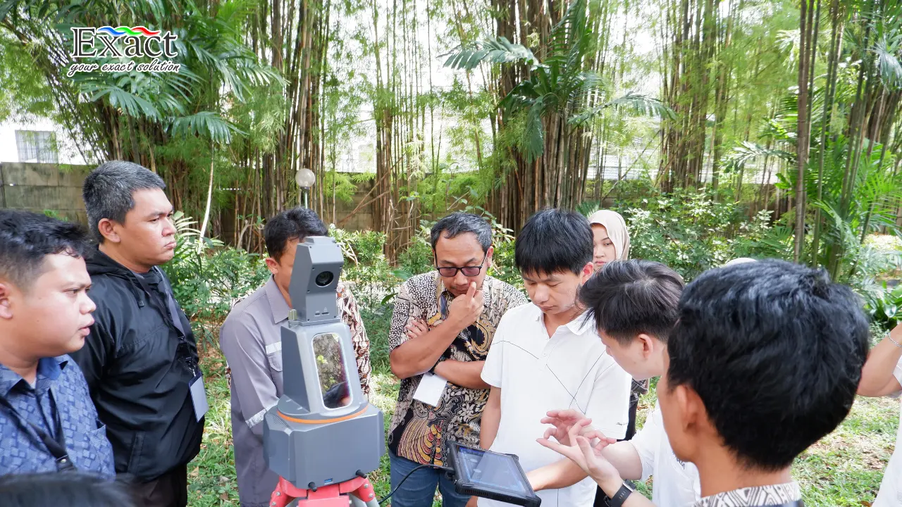
During the field presentation agenda, we saw first-hand several revolutionary instrument line-ups designed to capture reality quickly and precisely. Here is an overview of the device capabilities ready to assist our survey work:
- Topcon CR-P1: This is a premium-performance scanner with a very compact and lightweight physical form, weighing only 4.4 kilograms. Despite being small, this machine records data at high speeds of up to 2 million points per second. It is capable of scanning distances up to 400 meters, making it robust for mapping wide spans of tall buildings or high-voltage power grids. The CR-P1 is also equipped with a visual scanning status indicator (LED ring) so we know the tool is recording without having to look at its screen closely.
- Topcon ESN-100: This smart scanner device is designed so that work can be fully completed in the field. Its flagship feature is the Automatic Self-leveling system that works simply by pressing one button, making it very user-friendly without requiring complex surveying experience. The ESN-100 features automatic target prism detection technology up to a 100-meter range, an automatic combining scan data feature, and the ability to compare today’s scan data with yesterday’s.
- EliteScan T1000: As part of the scanning technology ecosystem showcased at the One Day Seminar, this tool completes our smart device options in facilitating digital surveys, recording high-resolution reality capture, and simplifying the pace of point cloud data management on construction sites.
Slope Monitoring and Dam Monitoring Solutions Using Robotic Total Station
Besides 3D scanning, we are also challenged to ensure the safety of large-scale infrastructure. Shifts in mine excavation walls or dam bodies often occur without being visible to the naked eye. If we still use conventional methods—where staff stand to find telescope targets, manually illuminate instruments, and then record measurement numbers one by one—we waste a lot of time.
We must shift to using Slope Monitoring and Dam Monitoring Solutions Using Robotic Total Stations that run autonomously without human labor. Through smart series Robotic Total Station (RTS) instruments like the MSAXII from Topcon, the stages of target tracking (Scan Search), locking (Auto Pointing), to periodic monitoring rotations are completely carried out by automatic motors.
A successful scenario of Slope Monitoring and Dam Monitoring Solutions Using Robotic Total Stations has been seen at the Sindangheula Dam. The configuration is highly systematic; we install 1 RTS station unit on a safely protected pillar, around 30 target prism points embedded across the monitoring plane (dam wall or cliff slope), and then connect it to 1 Data Processing computer machine.
This measurement machine is fully commanded by the MSP RAPID software system. Here is its workflow:
- MSP RAPID PC / Mobile: We utilize this core software to set the monitoring rotation schedule (e.g., every 2 hours) for 24 hours a day. The tool will aim at the points, then transmit its observation records to the office server via GPRS, GSM cellular, or UHF radio connections.
- DataChecker and StarPro: On the office server side, the DataChecker software module cleans raw data from false reading reflections. Next, the StarPro analytical module calculates the final points by referring to the least square adjustment method.
- Automatic Alarm Notifications: The device will instantly share graphical notifications of measurement point change history. If slope movements exceed the technical danger limits we set, the program immediately distributes physical siren notifications, sends electronic alert messages via email, or real-time SMS to our numbers. We can immediately evacuate construction workers.
Integration of Point Cloud Data into BIM Systems for Construction Verification
Uniting records of billions of points from various corners of a project area (scan world) requires precise position merging techniques, called Point Cloud Registration. We can stitch our scans using a variety of methods. We can use the help of reference sphere targets in the field (Target Based), stitch direct visual object overlaps (Cloud to Cloud), or use the Iterative Closest Point (ICP) algorithm.
Thanks to cutting-edge data processing applications like MAGNET Collage, we process these measurement captures without hurdles. However, the true potential of this technology only opens wide when we apply the Integration of Point Cloud Data into BIM Systems for Construction Verification.
Instead of just making the point cloud a visual image, we export our cleaned data into the utility-layered analytical ecosystem from ClearEdge3D for Building Information Modeling (BIM) management.
- EdgeWise: This advanced application extracts complex infrastructure pattern geometries from abstract point cloud sets. This tool tracks piping installation networks, air ventilation, and industrial structural steel pillar frames, then computationally converts them directly into CAD-based BIM models.
- Verity: This precision quality control software is used to analyze and compare point clouds of actual physical buildings that have just been cast (as-built) with the initial BIM file design models.
By executing the Integration of Point Cloud Data into BIM Systems for Construction Verification stages alongside the Verity utility, the system presents instant clash detection controls brightly colored. If the construction execution team misses by 3 centimeters when building a pillar foundation, Verity’s graphical analysis reports it to us that very second. We are capable of immediately rectifying structural errors that same day to avoid costly repeated demolitions at the end of the project.
Accuracy is Our Absolute Priority
All these adoptions of digital transition guide our operations toward extremely rapid survey time efficiency targets. Obtaining comprehensive 3D area terrain models in a single tap without the hassle of measuring manual boundaries is a fantastic mechanical leap. However, as the insightful message conveyed by Mr. Agung Syetiawan from BRIN at the end of his seminar session, borrowing the words of legendary lawman Wyatt Earp:
“Fast is fine, but Accuracy is everything.”
This motto affirms that our super-fast daily work pace must not compromise spatial metric accuracy. The precision of Terrestrial Laser Scanner measuring tools and the calculation precision of automated Robotic Total Station instruments supported by reliable software algorithms ensure we get both speed and accuracy without exception.
Frequently Asked Question
Q: What are the specific advantages of using a Terrestrial Laser Scanner (TLS) if I am already used to GNSS/Total Station methods?
Spatial point collection with TLS instruments can target millions of field shape coordinates safely and massively without direct touch methods (remote sensing). The extreme object density resolution from point cloud models suppresses design interpretation miscalculations that usually arise due to the scarcity of conventional survey observation point distributions (for example, stockpile volume calculations that are often unrealistic).
Q: How does mapping software recognize the border between pure land surfaces and shrub or forest vegetation?
Through a computer filtering stage dubbed Ground Classification, the algorithm software reads diverse data reflection patterns. The profile shapes of tall plant canopies, man-made infrastructure structures, and buildings will be identified as residual non-ground models to subsequently be “cleaned” or “removed” from the display. We are then left with a smooth bare earth relief profile known as a Digital Terrain Model (DTM).
Q: In the matter of dam monitoring, where is the real advantage of combining Robotic Total Station tools with the MSP RAPID software system?
Our manual monitoring operations require staff on daily watch highlighting prism telescopes with the risk of metric reading errors. Using the Robotic Total Station platform, the MSP RAPID PC device commands the Total Station at a safe pillar post fully automatically 24/7. The machine shoots all reference pillar networks and deformation prisms on the dam construction according to daily time intervals, calculates them instantly, and then triggers a Level 1 Alarm early protection (in the form of siren sound alarms, SMS or Email dispatches) if the shift point measurement exceeds the structure’s technical design safety limits.
Q: Why do the ClearEdge3D EdgeWise and Verity utilities play a vital role in our building construction verification projects?
The EdgeWise program accelerates the detection and conversion of point cloud cross-sections of difficult infrastructure like factory facility piping geometry networks into pure BIM CAD objects. In another inspection line, the Verity system compares the point cloud recording results of real building structures currently under construction (as-built actual data) in layers with the original BIM design file master drawings, validating and marking space clash deflections to reduce on-site builder errors.
Contact PT. Exact Global Teknologi
We consistently support your corporate measurement activities’ digitalization steps to transition to future methodologies. If you are ready to adopt the efficiency of 3D spatial scanners (ranging from Topcon CR-P1 series, ESN-100, hybrid total station scanner GTL-1200, GLS-2200 series), MSAXII automatic monitor Robotic Total Stations, as well as MSP RAPID analysis software and ClearEdge3D utilities:
Website : ww.exactglobal.co.id
Email : marketing@exactglobal.co.id
WhatsApp : +62 812-9252-3900