Building Infrastructure Digital Twins: A Guide to Millimeter-Level 3D Mapping for Complex Projects
In large-scale infrastructure projects, a deviation as small as 5 millimeters can trigger delay penalties and field rework costs amounting to hundreds of millions of rupiah. This article explores how implementing an Infrastructure Digital Twin using the Topcon CR-P1 3D Laser Scanner transforms Quality Assurance/Quality Control (QA/QC) workflows directly in the field. With a scanning speed of 2 million points per second and a 3D spatial accuracy of 2 mm, engineering teams can capture the complex geometric details of physical assets in real time. Through a Zero Office Post-Processing workflow and Scan-to-BIM software integration, this 3D reality capture technology provides absolute spatial certainty to detect discrepancies early, prevent costly field rework, and protect project profit margins.
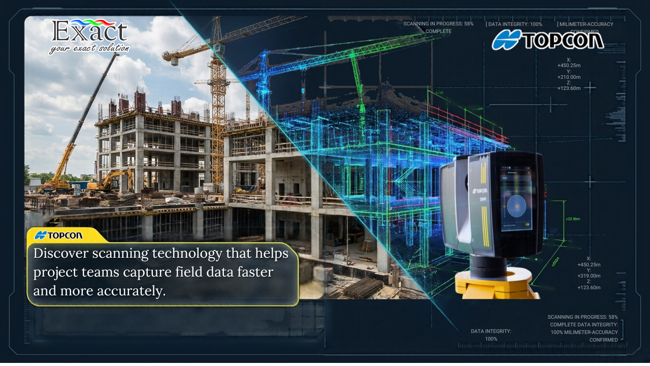
Did you know that an unnoticed discrepancy of just 5 millimeters in a bridge girder alignment or structural steel frame can propagate into hundreds of millions of rupiah in delay penalties, structural retrofitting, and field rework?
Across Indonesia’s expanding infrastructure landscape—from high-rise commercial towers and industrial processing facilities to long-span bridges and elevated toll roads—engineering teams face constant pressure to deliver projects on schedule and within budget. Traditional survey methods relying on tape measures, optical levels, or manual total stations simply cannot capture the millions of geometric data points required to represent complex physical assets accurately. When design models do not match actual field conditions, unexpected clashes occur during installation, forcing expensive site modifications and schedule slip.
To overcome these challenges, progressive engineering and survey firms are shifting toward building an Infrastructure Digital Twin with 3D Laser Scanning. By capturing a complete physical asset using a high-precision Terrestrial Laser Scanner (TLS) like the Topcon CR-P1, we create an exact digital replica that mirrors real-world geometry down to the millimeter. This spatial foundation powers accurate As-built documentation, accelerates Building Information Modeling (BIM) verification, and enables proactive Construction rework prevention throughout the project lifecycle.
In this guide, we break down eight key listicle pillars showing how 3D reality capture technology transforms field workflows, elevates quality control, and delivers complete spatial certainty for complex engineering projects across Indonesia.
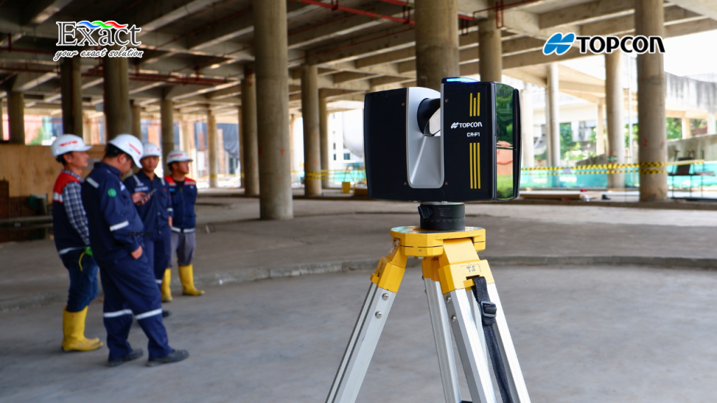
1. Capturing Reality at a Scanning Speed of 2 Million Points per Second
In large-scale infrastructure projects, field survey time is directly tied to site safety and project productivity. Halting site operations, stopping heavy equipment traffic, or securing hazardous work zones for hours to perform manual measurements drags down project momentum and inflates operational costs.
Using advanced 3D laser scanners like the Topcon CR-P1, we achieve a Scanning speed of 2 million points per second. This rate represents a 16-fold speed increase compared to conventional scanning instruments. A complete, 360-degree full-dome scan that used to require nearly fifteen minutes now finishes in approximately 1 minute.
FIELD SCANNING SPEED & DENSITY COMPARISON MATRIX
|
Metric / Parameter |
Legacy Laser Scanners |
Topcon CR-P1 System |
|
Data Capture Speed |
~125,000 points/sec |
Up to 2,000,000 pts/sec |
|
Full-Dome Scan Time |
10 to 15 minutes |
~1 minute |
|
Comparative Velocity |
Baseline (1x speed) |
16x faster capture rate |
|
External Photo Time |
1 to 3 minutes |
2 seconds (PanoCam) |
|
Total Station Setup Time |
High (manual leveling) |
Fast (quick-release mount)| |
This high-speed data capture creates a High-resolution 3D point cloud containing millions of individual coordinate points. Every beam bounce records precise X, Y, and Z spatial positions alongside signal intensity values. When mapping dense pipe networks in process plants, intricate roof trusses in airport terminals, or active excavation sites, this speed allows our survey crews to gather dense geometric data without delaying active construction trades.
Furthermore, when true-color visualization is required, the Topcon CR-P1 offers dual camera options. We can utilize its internal 13 MPx HDR camera or attach an external panoramic camera (such as the Ricoh Theta Z1) on its top accessory bay. The external panoramic camera captures full 360-degree color imagery in just 2 seconds per station. This rapid imagery capture allows our teams to colorize massive point clouds instantly while keeping field crews moving smoothly across large job sites.
2. Achieving 2 mm 3D Accuracy for Millimeter-Level Spatial Certainty
Speed means very little if spatial measurements lack geometric rigor. High-rise structures, precast concrete assemblies, and mechanical equipment pads require millimeter-level precision to ensure structural elements fit together perfectly during assembly.
The Topcon CR-P1 delivers a 2 mm 3D accuracy at a 10-meter distance (and 3.5 mm at 25 meters), supported by a systematic ranging error of just ±1 mm. This tight measurement tolerance ensures that every surface contour, column center, and flange face is captured with absolute fidelity.
TOPCON CR-P1 HARDWARE SPECIFICATIONS
|
Technical Features |
Specification Metric / Capability |
|
Maximum Scanning Range |
Up to 400 m (CR-P1 L model) |
|
3D Spatial Accuracy |
2 mm at 10 m / 3.5 mm at 25 m |
|
Distance Ranging Error |
±1 mm systematic error |
|
Angular Precision |
19 arcseconds |
|
Dual-Axis Compensator |
Levels each scan to 19 arcsec accuracy (±2° range) |
|
Physical Instrument Weight |
4.4 kg (including internal battery) |
|
Laser Safety Class |
Class 1 eye-safe laser |
|
Weather Protection |
IP54 water and dust resistance rating |
To maintain measurement accuracy on rugged job sites, the CR-P1 incorporates an automatic dual-axis compensator. This internal system levels every scan dataset with an accuracy of 19 arcseconds across a ±2° tilt window. Even if the carbon fiber tripod experiences minor vibrations or ground settling from nearby machinery, the compensator maintains true gravitational horizontal alignment.
We also benefit from a physical instrument weight of only 4.4 kg, including the internal battery. Combined with a quick-release mounting mechanism, field surveyors can unlatch the scanner, ascend stairwells, navigate tight scaffolding decks, and remount the instrument in seconds. This blend of lightweight portability and millimeter precision gives us Improved field surveying efficiency across every phase of construction.
3. Mastering Resection and Cloud-to-Cloud Registration Methods
A single laser scan captures only what lies directly within the instrument’s line of sight. To map an entire infrastructure asset—such as a multi-story building, a long highway corridor, or a sprawling water treatment plant—we must combine dozens or hundreds of individual scan setups into one unified coordinate system. This stitching process is called registration.
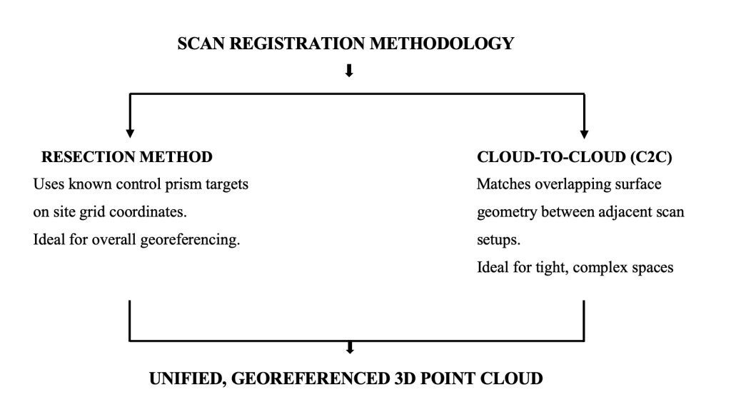
Using Topcon Collage Site field software, we employ both Resection and cloud-to-cloud registration methods directly on a rugged field tablet.
Resection Registration Method
When working on established construction sites with survey control networks, we position the scanner at an arbitrary location and target known survey control prisms placed around the site boundary. The software calculates the scanner’s exact spatial position and orientation within the project grid coordinates. This method guarantees that all point cloud data aligns perfectly with original engineering blueprints and GIS base maps.
Cloud-to-Cloud Registration Method
In enclosed or complex spaces where control targets are obstructed—such as congested MEP rooms or narrow building corridors—we utilize cloud-to-cloud registration. The software analyzes millions of overlapping 3D surface points between adjacent scan locations, automatically locking the point clouds together without requiring physical targets.
By combining resection and cloud-to-cloud algorithms on site, we eliminate blind spots, verify point cloud alignment immediately, and ensure zero data gaps before our survey crew leaves the job site.
4. Streamlining Bridge and Elevated Infrastructure Inspection
Inspecting critical public assets like highway overpasses, cable-stayed bridges, elevated rail lines, and high-voltage power corridors poses significant safety challenges. Traditional inspection approaches require inspectors to climb scaffolding, operate bucket trucks in active traffic lanes, or work at dangerous heights near energized lines.
Deploying a long-range Terrestrial Laser Scanner (TLS) transforms how we execute Bridge and elevated infrastructure inspection. The Topcon CR-P1 L model features a scanning range extending up to 400 meters. This extended reach allows our engineering teams to set up the instrument in a designated “green zone”—completely clear of active road traffic, river currents, or hazardous steep slopes.
ELEVATED INFRASTRUCTURE & HAZARDOUS SURVEY APPLICATIONS
|
Infrastructure Type |
Primary Survey Challenge |
CR-P1 Solution Workflow |
|
Long-Span Bridges |
Inspection over water & active traffic zones. |
400m range scans pier deflection from riverbanks. |
|
High-Voltage Power Lines |
High-altitude targets & electrical hazards. |
Remote 3D scanning clears safety buffer zones |
|
Tunnels & Excavations |
Confined space risks & overbreak calculations |
Rapid 1-min scans capture wall profiles safely |
|
Slope & Cliff Hazards |
| Unstable ground & rockfall danger to field crews |
Resection setup from safe boundary positions |
From a single secure location, we scan high-altitude bridge piers, stay cables, structural steel girders, and overhead power cables. The millimeter-level point cloud captures subtle structural deflections, concrete spalling, deck sag, and surface wear.
When inspecting underground transport tunnels or deep excavations, we pair CR-P1 point cloud data with specialized software like Aplitop TcpTUNNEL or TcpScancyr. The system automatically generates cross-sectional profiles along the tunnel alignment, calculates concrete shotcrete thickness, and highlights excavation overbreak or underbreak areas instantly. This remote scanning capability preserves crew safety while delivering rich geometric records for structural condition assessments.
5. Automating Model Extraction with Verity and EdgeWise Software Integration
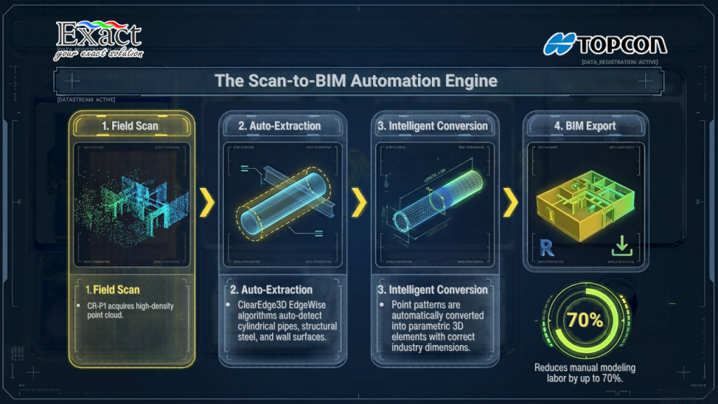
Capturing billions of 3D points in the field solves the data collection puzzle, but manually modeling every pipe, beam, duct, and wall in CAD software can take hundreds of hours of tedious drafting. To convert point cloud datasets into intelligent 3D BIM elements efficiently, we rely on Verity and EdgeWise software integration.
AUTOMATED POINT CLOUD TO BIM WORKFLOW PIPELINE
|
Step 1: Field Scan Step 2: On-Site Process Step 3: Auto-Extraction Step 4: BIM Export Step 5: Verification |
Acquire high-density point cloud via Topcon CR-P1 TLS Register scans via Collage Site field software ClearEdge3D EdgeWise auto-detects pipes, steel, walls Export intelligent parametric objects directly to Revit Verity compares as-built point cloud against BIM model |
Automated Feature Extraction with EdgeWise
ClearEdge3D EdgeWise uses automated feature recognition algorithms to process raw point cloud data. The software automatically identifies cylindrical pipe runs, structural steel shapes, conduit banks, and wall surfaces from the point cloud. Instead of manually tracing points, EdgeWise extracts these geometry elements automatically, assigns correct industry dimensions, and exports parametric models directly into Autodesk Revit. This automation reduces manual modeling labor by up to 70%.
Automated Construction Verification with Verity
Once construction trades install structural steel, concrete decks, or MEP systems, we perform Building Information Modeling (BIM) verification using ClearEdge3D Verity. Verity compares our newly scanned physical as-built point cloud directly against the intended 3D BIM design model.
The software automatically analyzes every installed element, color-coding components based on installation accuracy:
- Green Elements: Installed within specified design tolerances.
- Yellow Elements: Installed out of position, exceeding variance limits.
- Red Elements: Missing components or major physical clashes.
By identifying out-of-tolerance steel beams or misplaced mechanical ductwork immediately after installation, Verity allows us to correct errors before downstream construction trades begin work.
6. Elevating Project Quality Assurance/Quality Control (QA/QC) in the Field
Traditional site inspection methods rely on spot-checking isolated locations with hand tools, optical levels, or tape measures. Spot-checking leaves wide unmeasured gaps across large job sites, allowing physical defects to go unnoticed until finishing trades encounter installation clashes.
Implementing 3D laser scanning transforms Project Quality Assurance / Quality Control (QA/QC) into a comprehensive, coverage-driven process.
TRADITIONAL SPOT-CHECK QA/QC WORKFLOW:
[Manual Measurement] ➜ [Sparse Sample Points] ➜ [Hidden Defects Unnoticed]
➜ RESULT: Costly clashes during trade installation!
3D TLS FULL-COVERAGE QA/QC WORKFLOW:
[CR-P1 360° Scan] ➜ [Millions of 3D Coordinates] ➜ [Instant Surface Analysis]
➜ RESULT: 100% Surface coverage, zero hidden errors!
Using Topcon Collage Site software on a field tablet, our site engineers execute full surface audits while standing directly at the job site. For concrete floor slab pours, the software provides specialized elevation checking routines. Seconds after the scanner completes its rotation, the tablet displays a color-coded surface elevation map:
- Red Areas: High spots exceeding elevation tolerances.
- Blue Areas: Low spots requiring additional concrete mix.
- Green Areas: Flat surfaces meeting strict design specifications.
When paving industrial warehouse floors or logistics slabs, this real-time elevation feedback allows concrete finishing crews to fix high or low spots while the concrete remains wet. By verifying surface flatness before concrete hardens, we prevent costly post-curing grinding, slab topping, or floor rebuilding.
7. Driving Construction Rework Prevention and Real-Time Field Progress Monitoring
In complex construction environments, unaddressed field discrepancies lead to compounding errors. A misplaced pipe header or slightly misaligned structural column can disrupt ductwork, electrical trays, and drywall framing across an entire building floor.
CONSTRUCTION REWORK & SCHEDULE IMPACT COMPARISON
|
Project Phase |
Traditional QA/QC Impact |
3D TLS Reality Capture |
|
Discrepancy Detection |
Late (during trade install |
Early (immediately post-pour |
|
Correction Method |
Cut, grind, re-fabricate |
Adjust wet mix or layout |
|
Impact on Project Margin |
High profit erosion |
Zero rework expenditure |
|
Progress Monitoring |
Subjective site estimates |
Objective 3D volume audit |
|
As-Built Accuracy |
Estimated redline drawings |
100% True-reality point cloud| |
By adopting a reality capture workflow, we turn 3D laser scanning into a primary engine for Construction rework prevention. Capturing high-density point clouds after every major construction pour creates an unalterable spatial record.
Furthermore, this spatial data enables Real-time field progress monitoring. On earthworks and site excavation projects, we use the Topcon Raster Scan feature in Collage Site to compare ground elevation data captured today against yesterday’s baseline scan. The tablet automatically calculates excavated cut and fill volumes, generating visual progress heatmaps directly on site. Project managers can verify daily subcontractor earthmoving claims, track material stockpiles, and adjust equipment deployment with complete confidence.
8. Ensuring Cloud Collaboration for Improved Field Surveying Efficiency
As modern infrastructure projects scale up, seamless communication between field survey crews and office engineering teams becomes essential. Storing massive point cloud files on local hard drives or shipping physical USB drives creates data silos, version control issues, and communication lags.
We bridge this gap using the Topcon Enterprise cloud platform. Topcon Enterprise maps all field scans, design surfaces, and 3D models over a georeferenced web browser interface.
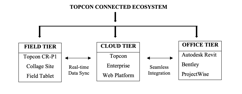
Project managers, BIM coordinators, and structural engineers log into the web cloud interface from anywhere to inspect survey progress in real time. Office engineers can add digital annotations, highlight design changes, or redline maps directly within the cloud browser. These instructions synchronize instantly to the surveyor’s field tablet on site, keeping field crews aligned with the latest engineering plans.
Furthermore, Topcon cloud tools integrate directly with industry-standard environments like Autodesk BIM 360 and Bentley ProjectWise. Surveyors and designers pull 3D point cloud datasets directly into AutoCAD, Revit, or MicroStation without manual file conversions, delivering Improved field surveying efficiency across the entire digital thread.
Exact Global Teknologi: Your Reality Capture Partner in Indonesia
Successfully deploying 3D reality capture technology across complex infrastructure projects requires more than just purchasing advanced hardware. It demands complete local technical support, specialized software training, equipment calibration, and workflow consulting.
Exact Global Teknologi is Indonesia’s leading authorized distributor and solution provider for Topcon positioning, surveying, and reality capture technologies. Our team of geospatial professionals works alongside contractors, engineering consultants, government agencies, and survey firms across Indonesia to implement robust Infrastructure Digital Twin with 3D Laser Scanning solutions.
We provide comprehensive sales, equipment rental, technical support, field training, and software integration services tailored to your project requirements.
Contact Information:
- Company Name: PT. Exact Global Teknologi
- Official Website: www.exactglobal.co.id
- Email Marketing: marketing@exactglobal.co.id
- WhatsApp Support: [+62 812-9252-3900]
Frequently Asked Questions (FAQ)
1. What is an Infrastructure Digital Twin, and how does 3D laser scanning create it?
An Infrastructure Digital Twin is a precise 3D digital replica of a physical structure or civil asset. A Terrestrial Laser Scanner (TLS) like the Topcon CR-P1 creates this digital twin by firing laser beams millions of times per second to capture the exact geometric dimensions of the physical asset as a High-resolution 3D point cloud. This point cloud serves as the spatial baseline for As-built documentation, facility management, and ongoing structural monitoring.
2. How fast is the Topcon CR-P1 compared to conventional 3D laser scanners?
The Topcon CR-P1 operates at a Scanning speed of 2 million points per second, making it approximately 16 times faster than legacy laser scanners. A complete 360-degree full-dome scan finishes in about 1 minute. When paired with an optional external panoramic camera, full-color 360-degree imagery is captured in just 2 seconds per station.
3. What spatial accuracy does the Topcon CR-P1 deliver for complex engineering projects?
The CR-P1 delivers a 2 mm 3D accuracy at a 10-meter distance (and 3.5 mm at 25 meters), with a systematic distance ranging error of ±1 mm. It also features an automatic dual-axis compensator that levels every scan dataset with an accuracy of 19 arcseconds across a ±2° tilt range, ensuring true horizontal precision on active job sites.
4. How do Verity and EdgeWise software integration simplify Scan-to-BIM workflows?
ClearEdge3D EdgeWise automatically detects pipe runs, structural steel beams, ductwork, and wall geometries directly from point clouds, turning raw scan data into intelligent parametric BIM objects automatically. ClearEdge3D Verity compares the scanned as-built point cloud against the original 3D BIM design model, automatically identifying misplaced components, out-of-tolerance elements, or physical clashes.
5. How does 3D reality capture drive Construction rework prevention on job sites?
By capturing dense point clouds immediately after major concrete pours or trade installations, field teams perform real-time surface flatness audits and clearance checks using Topcon Collage Site software on a field tablet. Identifying elevation errors or layout variances while materials remain workable allows crews to fix defects on site immediately, preventing expensive post-curing repairs or structural retrofits.
6. Can the Topcon CR-P1 scan elevated structures or hazardous areas safely?
Yes. The CR-P1 L model features an extended scanning range of up to 400 meters. Using the Resection and cloud-to-cloud registration methods, survey crews can position the instrument in a safe “green zone” away from active traffic, river channels, or steep cliffs while accurately capturing high-altitude targets like bridge piers, stay cables, and overhead electrical lines.